Home
/ 555 Timer Ic Schematic Diagram : Ecen 2250 Mydaq Experiment 1 Capacitors And The 555 Timer : With this information you will learn how how the 555 works and will have the experience to build some of the circuits below.
555 Timer Ic Schematic Diagram : Ecen 2250 Mydaq Experiment 1 Capacitors And The 555 Timer : With this information you will learn how how the 555 works and will have the experience to build some of the circuits below.
555 Timer Ic Schematic Diagram : Ecen 2250 Mydaq Experiment 1 Capacitors And The 555 Timer : With this information you will learn how how the 555 works and will have the experience to build some of the circuits below.. We have seen in the last few tutorials that the 555 timer can be configured with externally connected components as multivibrators, oscillators and timers, with timing intervals ranging from a few microseconds to many hours. The following example shows the 555 timer in bistable mode. Simple 555 timer circuits & projects. Derivatives provide two or four timing circuits in one package.it was commercialized in 1972 by signetics. Various light actuator and relay driver circuits are also further enclosed.
The entire cell phone signal jammer circuit can be powered up using a 9v battery. It is connected to ground as usual. Figure 1 is the pinout and functional block diagram for the 555 timer ic. How much voltage and current will come. The block diagram of a 555 timer is shown in the above figure.
How To Generate Pwm Signal Using 555 Timer Ic Laptrinhx from www.electronicshub.org These on off intervals can be adjusted by varying the 555 timer output and number of counter outputs. The standard 555 timer ic is made of 2 diodes. 555 timers are very popular in electronics. As discussed in the above section, the ic is in its standard monostable mode. 8.power or vcc pin 1. 555 ic timer block diagram 555 ic timer block diagram. From our earlier discussions we know that for a 555 in the delay timer mode, the delay could be accurately managed through a single external resistor and one capacitor. Now, you can easily design the different timer circuits of 1minute,5 minute,10 minute and 15 minute using 555 timer ic with ease.
We hope that you have got a good knowledge of 555 timer ic and different timer circuits using the same.
Once this switch is pushed, the circuit pulls its output to a. 8.power or vcc pin 1. The output of the 555 timer is fed to the amplifier circuit through a 1uf electrolytic capacitor. Now as shown in figure, there are eight pins for a 555 timer ic namely, 1.ground. This controlling can be done by selecting the appropriate values for the resistor r1,r2 and capacitor c1. The 555 timer ic is an integrated circuit (chip) used in a variety of timer, delay, pulse generation, and oscillator applications. Simple 555 timer circuits & projects. Resistive network consists of three equal resistors and acts as a voltage divider. Derivatives provide two or four timing circuits in one package.it was commercialized in 1972 by signetics. Let us discuss in detail about this circuit. The following example shows the 555 timer in bistable mode. Basic 555 monostable multivibrator circuit. The timer's internal circuitry is largely responsible for this triggering but it is also caused stray or installed capacitance at the trigger input of the timer.
555 timer was first introduced by signetics corporation in 1971 as se555/ne555. Resistive network consists of three equal resistors and acts as a voltage divider. The circuit diagram to operate the 555 ic in astable mode is shown be The 555 timer is a simple integrated circuit that can be used to make many different electronic circuits. Or separate the on and off switch for a machine.
Time Delay Relay Using 555 Timer Proteus Simulation And Pcb Design from i2.wp.com The following example shows the 555 timer in bistable mode. 555 timer bistable example circuit. If you are a beginner in electronics, you should learn the basics about a 555 timer ic, before you attempt to build 555 timer circuit or a full 555 timer project. Sir do u have any igbt or mosfet 12v dc to 48v dc ckt diagrams. The entire cell phone signal jammer circuit can be powered up using a 9v battery. 8.power or vcc pin 1. 555 datasheet 555 duty cycle 555 metronome 555 reset function 555 time delay relay inverted 555 timer pulse generator. Various light actuator and relay driver circuits are also further enclosed.
We hope that you have got a good knowledge of 555 timer ic and different timer circuits using the same.
How much voltage and current will come. In 2017, it was said over a billion 555 timers are produced. Pin diagram of 555 ic. This integrated circuit can be used in a variety of ways from which the basic one is to produce accurate and stable delays in electronic circuits.additionally, it is available in 8 pin dip and 14 pin dip. The following example shows the 555 timer in bistable mode. Being an integral part of electronics project, 555 timer ic is very often used in simple to complex electronics projects. The switch s1 is used to turn on and turn off the cell phone jammer. Its name is derived from three 5k ohm resistors ,connected in series used in it.the timer ic can produce required waveform accurately. The 555 timer ic is an integrated circuit (chip) used in a variety of timer, delay, pulse generation, and oscillator applications. Adjustable on off timer(using 555 astable mode) in this circuit a timer with cyclic on off operations is designed. Note this ckt diagram runs or burnt this type. This pin has no special function what so ever. Let us discuss in detail about this circuit.
This pin has no special function what so ever. Referring to the timing diagram in figure 3, a low voltage pulse applied to the trigger input (pin 2) causes the output voltage at pin 3 to go from low to high. The 555 timer ic is an integral part of electronics projects. Internal circuit diagram of 555 ic. In 2017, it was said over a billion 555 timers are produced.
What Is A 555 Timer Ic Using 555 Timer Ic For Monostable Circuit Ettron from ettron.com The circuit diagram to operate the 555 ic in astable mode is shown be One reduces the trigger sensitivity and the other will double the output pulse duration without increasing the r1 and c1 values. Pin diagram of 555 ic. This integrated circuit can be used in a variety of ways from which the basic one is to produce accurate and stable delays in electronic circuits.additionally, it is available in 8 pin dip and 14 pin dip. Its name is derived from three 5k ohm resistors ,connected in series used in it.the timer ic can produce required waveform accurately. In this category, we have handpicked some really useful 555 timer circuits which will be interesting to electronics engineering students and hobbyists alike. 555 datasheet 555 duty cycle 555 metronome 555 reset function 555 time delay relay inverted 555 timer pulse generator. The 555 timer ic is an integral part of electronics projects.
Once this switch is pushed, the circuit pulls its output to a.
Although the schematic looks correct, this basic circuit may actually have a few negative aspects. Each mode of operation indicates a circuit diagram and its output. The 555 timer ic is a very cheap, popular and useful precision timing device which can act as either a simple timer to generate single pulses or long time delays, or as a relaxation oscillator producing a string of stabilised waveforms of varying duty cycles from 50 to 100%. One reduces the trigger sensitivity and the other will double the output pulse duration without increasing the r1 and c1 values. Sir do u have any igbt or mosfet 12v dc to 48v dc ckt diagrams. 555 timer pin diagram and descriptions. Basic 555 monostable multivibrator circuit. These on off intervals can be adjusted by varying the 555 timer output and number of counter outputs. The entire cell phone signal jammer circuit can be powered up using a 9v battery. 555 timers are very popular in electronics. A collection of 555 circuits using the 555 timer as an astable oscillator with different duty cycles. Internal circuit diagram of 555 ic. Resistive network consists of three equal resistors and acts as a voltage divider.
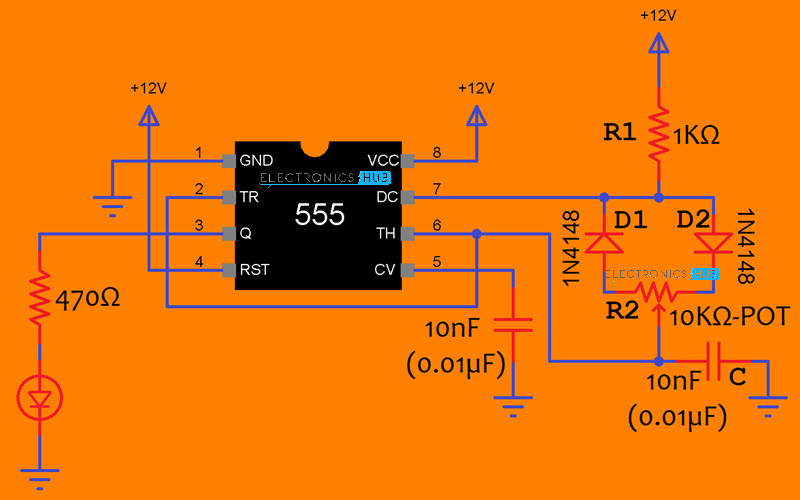
There are simple circuits for beginners and advanced engineers 555 timer schematic. When a 555 timer is operating in astable mode we obtain a pulse on the output pin whose on time (time high) and off time (time low) can be controlled.

